On a recent project here in San Francisco, I found myself looking at the site photo illustrated to the right and wondering about how I could make the process of modeling the cornice detail as simple as possible in AutoCAD Architecture.
The top shape of the cornice could probably be Extruded along a Polyline and the dentils could probably be Arrayed along two or three paths. However, I decided to make another Jig so I would have yet another tool ready for whenever this type of scenario comes up: the mighty Curtain Wall to the rescue.

Draw a closed Polyline shape to represent the cornice body as illustrated to the right.
Use the "Profile" command and Define a new Profile based on the closed Polyline shape. Set the Insertion Point as illustrated to the right. Because this shape will be used as the Top Frame Element within a custom Curtain Wall Style, its orientation and insertion point may appear a little odd. This is not the only way to define the shape but it does work.

Create a New Curtain Wall Style and name it something like "Cornice". Go to the "Primary Grid" Element setting and name it to "Dentil Spacing". Make sure the Orientation is set to Vertical and that the Division Type is set to Fixed Cell Dimension. Set the Cell Dimension to the distance you want between the dentils.

Go to the Default Cell Assignments Element and set it to "Default Infill". Rename "Default Infill" to "Fascia", set the Alignment to "Back" and the Panel Thickness to "1 1/2".

Go to Frames and rename the Default Frame to something like "Cornice Body". Set the Width and Depth values as they apply to the Close Polyline Shape used for the Profile Definition earlier (see illustration to the right).
Set the "Use Profile" checkbox and then pick the Profile from the drop-down list.

Go to the Mullions and rename the Default Mullion to something like "Dentils". Set the Width and Depth values. The Width is the value of the Dentil width as viewed from the front elevation. The Depth is the length of the dentil going into, or under, the cornice body. The height will be discussed later.
The "Y" Offset is used to push the Dentil forward of the fascia board. By default, these dentils would be centered on the centerline of the Curtain Wall because they are actually mullions. The -10" value is 1/2 of 1'-8" (20").

The final setting in this custom Curtain Wall Style is under the "Default Frame Assignments": make sure to set the "Used In" section to "Top" only as illustrated to the right.

In the illustrations to the right I show how your Cornice Curtain Wall Style may appear upon first use. Use the Height to control the height of the fascia board and the dentils.
Note:
This is just one quick solution I cooked up in a hurry. You can apply
these concepts in numerous ways to create all sorts of interesting solutions
for repetitive architectural features.

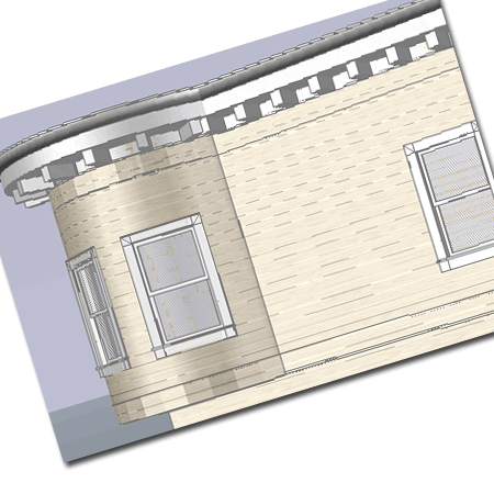
Illustrated to the right is the final product of my own efforts to create a quick solution for the cornice detail I needed on an existing building. Because I won't be modifying any of this work, exact dimensions won't be necessary; it just provides enough detail to make it realistic.
Note:
You can use the "CurtainWallReference"
command to set a CurtainWall Object to follow a Polyling Path. This is
how I not only got my cornice to curve around the round bay but also follow
around other classic bays on this building.
