After releasing an article on creating trim for Door and Window Styles in Architectural Desktop, I received numerous invitations to create similar custom content for other firms. Because of the high level of interest in this particular subject, I decided to expand on it. Below I will outline the steps involved in creating a Jig in Architectural Desktop and how this can be used to quickly add custom Display Components to numerous Objects, like Doors and Windows.
In the case of adding trim to Door and Window Styles, the majority of the work lies in Adding custom Blocks as Display Component Overrides for each Display Representation in which you want these custom components to display. At a minimum, you are likely to want trim for the Elevation, Model and Model High Detail Display Representations and because there are numerous Blocks to Add, this can be a really repetitious task [(number of Blocks) x (number of Display Rep. Overrides) x (number of Door or Window Styles)].
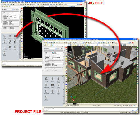
Another way to approach repetitious Display Representation customization is to avoid using Display Overrides and this can be done by making the customization work the default setting. The danger in making customization like this the default, is that you are likely to want other options and then they would have to be the Overrides. This is where a Jig comes in and what it does is allow you to set things as the default until you are ready to transport them to your working files (or library files).
Note:
Savvy ADT users might argue that once you have set Overrides on one Object
Style, all you have to do is create Copies of it and modify the Properties
to create all of the various permutations. I am just offering a new
trick to an old problem and I can pass my Jig on to you.
To create an ADT Jig, use a template file that is devoid of things you don't want to accidentally import into your working drawings. Be sure to use a template file that has the proper Display Representations for the Objects you intend to customize. In the illustration to the right I am using the "Aec Model (Imperial Ctb).dwt" and that might be okay for some but for others these default templates are notorious for introducing gobs of undesirable Objects and Settings ( like that irritating "G-Anno-Nplt" that is virtually impossible to Purge).
Once you have your clean file open and ready for configuration as a Jig, be sure to Name it in such a way that no one will ever use it as an office template file. Don't bother to introduce any Objects unless you really need to because the "Standard" Object Style should suffice.
In the illustration to the right I show that I have located the "Standard" Window Style and accessed its Display Properties tab via the "Window Style Properties" dialog box. At this point careful consideration has to be made with respect to those Display Representations you actually want to alter. In the case of adding custom window trim, I have decided to alter the "Elevation", "Model" and "Model High Detail" Display Representations. You may also choose to alter the "Plan High Detail" and/or "Sill Plan" to match the trim that will display in 3D Views.
Notice, and this is the most important part, that I have not used Style Overrides. That means that the changes I make will affect all Window Styles in this Drawing File that do not have their own Style Overrides.
For information on the Blocks used to create custom trim, see Trim your Doors and Windows in Architectural Desktop.
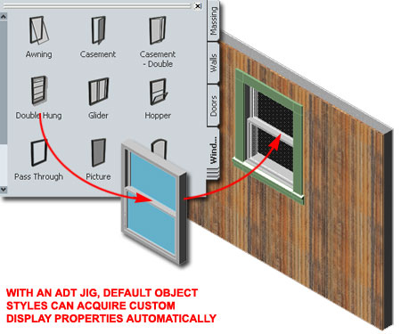
Once you have completed the work of setting all of the default Display Representations to produce the desired results, you can introduce default Objects Styles and observe how they will automatically acquire the new Display Representation settings. The key, of course, is that the Objects you introduce, cannot have Display Representation Style Overrides for the Representations you modified.
Illustrated to the right I show that I have completed my custom Window Trim Jig and imported one of the default Window Styles via ADT's Tool Palette. The default Double Hung Window automatically acquired the custom trim Blocks Added to the default Elevation, Model, Model High Detail and other Display Representations. It's almost magical when you see it in real-time.
You might assume that you are done now and all you have to do is import the modified Style into any working drawing where you want to use it. However, most working drawings have "Elevation", "Model", "Model High Detail" and other Display Representations so unless the cool new changes are set as Style Overrides, the Object will revert to the current default Display Representation settings. This is where the whole Jig concept completes its function. After the imported Object Style has acquired the new default Display Representation settings, go to the Style Properties of this Object and pick on the Style Override checkbox for each Display Representation you modified. I also recommend that you use the General tab and change the Style Name; maybe add the word "trim" or something. After completing this last bit of work, you can Copy the Style and import it into any other drawing file you want.
| Mouse | Right-click, Save Target As... |
|
|
You may download directly to your Desktop or other location "Door_Window_Trim_Standard_Wood_Jig.dwg". This file contains an example Jig for the discussion above and is based upon the default "Aec Model (Imperial Ctb).dwt" template file for Architectural Desktop 2006. |
| Keyboard |
You can easily expand on the Jig concept and create a variety of Jig files. You can even have a variety of Jigs just for Window Styles where different types of trim are added; like standard wood, stucco, pre-cast, etc. Once you have run an Object Style through a Jig, you can add it to a Library File and make a Palette Tool for easy retrieval later on. Some might decide to make the Jig itself a Library File but that can be a little risky and I don't recommend it.
In the sample Jig file that you can download to the left, I have used Mass Elements to create the Window trim. There is a set for the inside and the outside and you can change the Materials by going to the MassElementStyle dialog. If you want to alter the design of the trim, you can use Refedit on the Blocks I have inserted at the bottom of the drawing file. Mass Elements offer a number of editing tools so you should find that you can push, pull and cut to suite your needs. The insertion points are rather important and if you find that your modifications to the trim shift the placement on the Window Object, you may need to adjust Insertion Offset values - see Trim your Doors and Windows in Architectural Desktop for more information.